Disassembly
of Motorola Iridium Telephone.
After
it was announced by the media that the Motorola Iridium system would be
de-orbited I obtained an Iridium phone (very cheap, less than 1/100th of
original cost) and proceeded to pull it apart. Now that the system is back going
again I wish that the phone was still in one piece :-( However I thought that
others might learn from my disassembly of the phone...thus this web page.
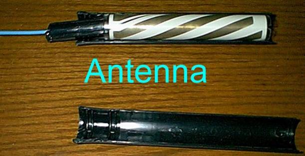
Disassembly
of the antenna
À
The
antenna is removed from the main body of the phone by pressing the antenna
release latch and rotating the antenna
À
I
snapped the connector off the base of the antenna.
À
There
is a circular end cap (disk) which is held in by the two black plastic halves of
the cylinder
À
To
pull the antenna apart I simply placed a screwdriver in the gap of
the
plastic
casing and prised it apart. The end closest to the phone is the place to
start otherwise the antenna insides may be damaged. The antenna
unit
is a clear plastic cylinder with "silver tracks"
on
it. The coax is coupled to the plastic
cylinder.
What
I found when I disassembled the antenna:
À
The
antenna is coupled to the coax using capacitive coupling?
À
The
antenna is a quadrifilar antenna, constructed using a clear plastic cylinder and
plated on "elements"
À
Blue
semi rigid coax connects the capacitive coupling to the antenna
socket
À
The
"elements" on the quadrifilar appear to be plated on silver. It looks like the
silver has partly oxidized.
À
There
is no preamp built into the antenna.
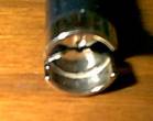
Above
picture shows an end view of the antenna coupler. This is inserted into the end
of the plastic tube. The coupler
is
soldered onto the blue coax. It may be hard to see from the picture but the
coupler is comprised of two ôhalvesö. There
is
an air gap between them. The coax seems to have shield soldered on one side,core on the other.
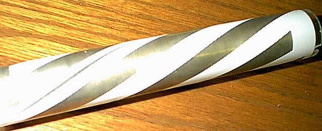
Above
picture is quadrifilar antenna. The
Iridium phone antenna looks similar to the Qualcomm GSP-1600 (used by
Globalstar) antenna. I wouldnÆt be
surprised if the antennas are very similar in Globalstar
units.
Battery
Compartment and Back Case of phone
À
The
batteries I received with the phone are Lithium Ion batteries. The battery pack
is a small ôboxö. Batteries are 3.? Volt.
À
They
batteries wrapping has lots of security holograms on them to state that they are
Motorola original products.
À
The
battery charger appears to be a switch mode device (very light). Can take 110 or
240V. Novel design means that it can take use straight or angled pins in mains
voltage socket via a small slide on adaptor.
À
The
battery charger plug on the low
voltage side is a unique design. It has a huge number of
contacts
À
The
cover for the battery compartment is constructed from thin plastic???mm. It can
be easily flexed between two fingers.
À
Inside
the back of the phone is a main wiring harness made from (Flat Plastic Cable)
FPC.
À
A
small PCB is found behind the antenna connector. It has several SMT components.
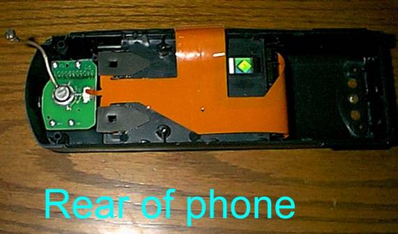
The
PCB at the LHS of this photo is mounted on the back of the antenna connector.
The coax originally went to the
main board.
Keypad
À
Thick
ôsiliconeö type rubber keypad presses onto ôbubbleö type switches on
PCB.
À
Illuminated
by SMT LED
SIM
Card and IMEI
À
The
SIM card is a full size ISO "credit card" sized card. The phone accepts the full
sized cards.
À
When
I acquired the phone it was missing the actual 'smartcard' portion of the
simcard.
À
Appear
to be a lot that can be done when the phone is powered up without the simcard. I
tested it however when the system was in "bankrupt" mode.
À
The
IMEI number is displayed inside the battery compartment.
À
The
card I have has an Australian address etc printed on it.
Main
PCB
À
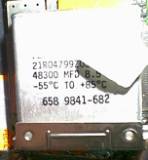
VERY
physically large capacitor (approx 60mm x 50mm x 10mm )
Has marked on it 48300 MFD 8.5
Volts.
À
Almost
all circuits well RF shielded with metal covers
À
Two
interesting looking "cans" made by Raytheon (Part number
RMPA-1620A-121)
and RMLA1620C122. I haven't been able to find product
info
sheets on these. Can anyone
help?
From
looking at the Raytheon RF components web page it seems obvious that the RMPA
component is the RF Power Amplifier. The RMLA is the RF low noise amplifier. The
frequency that these devices are centred on is likely to be 1620Mhz. The
RMPA-1620A-121
appears to have a LARGE number of pins. There are shielded cans on the back of
the PCB behind the PA module.
Large Metal Cover
The
large metal cover with the gold clips is the only one easy to remove. A
soldering iron, screwdriver and desolder braid can be used to free
this
cover.
Underneath are a load of chips made by
various
manufacturers Atmel, Temic, AD, Maxim etc. There is also a very
odd
shiny
silicon chip. Instead of being made with a plastic or ceramic case the ôlidö
looks
like it is made of glass!
À
These
chips appear to be the "brains" of the
phone.
I
guess that the AD7342XST is the DSP that handles the IMBE
codec??
An
Temic TSS4550-1A (Temic make speech recognition???)
An
Atmel AT28BV4 64K EEPROM
An
MAX3238 RS232 Driver
There
are various Motorola SC.. chips that I cannot identify..
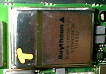 The photo on the left shows the
The
RMPA-1620A-121
module.
The photo on the left shows the
The
RMPA-1620A-121
module.
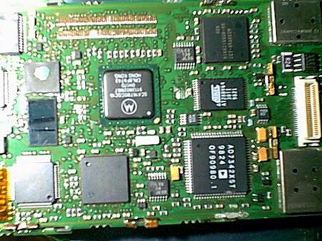 View
of a portion of the main board. It looks like this is the main processing area
of the phone.
View
of a portion of the main board. It looks like this is the main processing area
of the phone.
Manual
An
excellent spiral bound manual came with the phone. Interesting points from the
manual are:
À
GSM
cassette is available as optional extra
À
????????
What
I would like to know:
À
Are
any service manuals for this phone available? If so what are the part numbers
and where can they be obtained?
À
Are
any service manuals for the Iridium pager available? If so what are the part
numbers and where can they be obtained?
À
Is
there anything interesting that can be accomplished by having an Iridium phone
or pager without a subscription? Eg receive status reports from visible
satellites etc?
Any
feedback on my assumptions etc would be much appreciated. Please
e-mail